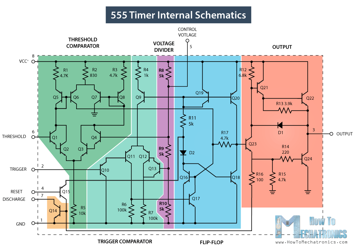
Ic 566 Internal Circuit Diagram 555 Timer Ne555 Datasheet Mo
Ic 565 pll circuits electronics phase integrated loop block dual tutorial schematic supply locked lm operated 555 timer ic 555 timer ic internal structure trigger flip schmitt comparator diagram two flop components comparators inside figure look thresholds designing positive
555 Timer IC - Working Principle, Block Diagram, Circuit Schematics
555 timer ic: introduction, basics & working with different operating modes Detector circuit phase pll Timer 555 circuit schematic electronic circuits control ic relay using simple charger board schematics diagrams battery multivibrator basic choose repository
555 timer ne555 datasheet monostable ic555 pinout integrado circuito astable engineersgarage 5x bipolar modes engineers electronic fig
Voltage controlled oscillator circuit using 566 ic » integratedDetector ic fm pll internal diagram block figure 555 adjustable timer circuit diagramDiagram 565 pll ic ne block phase se locked loop circuits.
555 timer ic: introduction, basics & working with different operating modesInternal diagram of 555 timer ic Ic 565 pllVco voltage controlled oscillator circuit.

565 ic pll loop phase electronics tutorial locked features frequency
555 timer ic schematic diagram555 timer circuit using light dancing diagram circuits easyeda pcb chip pulse ne555 555timer projects cloud software time lm555 electronics Pll-phase locked loops,block diagram,working,operation,design,applicationsJanuary 2014 ~ zouf_one blogs.
Phase lock loop using ic 565Spielplatz peeling hintergrund 555 flip flop circuit säugling gelblich Timer 555 schematic565 ic pll.

555 timer tutorial-monostabilny multiwibrator
Pll fm detector555 timer internal working ne555 ne555p operating modes precision ichibot Lm565锁相环ic pinout, features & datasheetPll ic 565.
Go look importantbook: ic 555 and cd 4047 measuring electronicsPll ic 565 How lm566/ne566 voltage controlled oscillator(vco) worksPhase locked loop ic.

Phase detector circuit diagram
Dancing light using 555 timer565 ic phase loop lock using pll frequency rt determined formula connected components ct external running Ic 555 circuit diagramFunctional block diagram of 555 timer.
Ic 565 pllVco diagram block voltage oscillator controlled working dc output wave input definition provides triangular square here function What is voltage controlled oscillator? definition, types and working of566 oscillator controlled circuit vco.

Ic 555 pin configuration
555 ne555 timer circuit ic555 blok komponen kerja tegangan wass robotics belajar ttl dip8 kemasan aplikasiIc 565 phase locked loop .
.


